
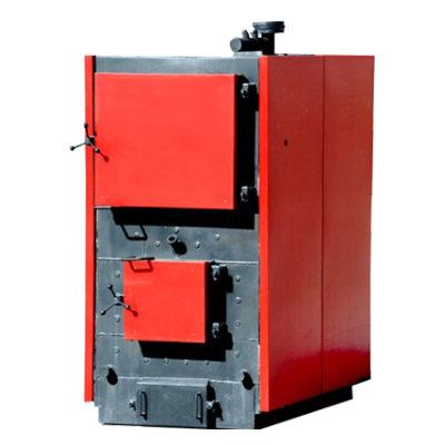
А series steel hot-water solid-fuel boilers meant for heating buildings and dwelling, household municipal, and manufacturing purpose with up to 95°С heat carries temperature, by using charcoal, wood material, wood refuse, fuel briquets or pellets in the capacity of fuel; as well as high-temperature hot water with intermediate heat exchanger’s usage.
It is allowed to use all types of coals in the quality of fuel. The copper’s design allows to use, heat which is allocated when burning different types of low-calorie solid fuel, most effectively. The greatest efficiency of copper is reached during the rated power work, at the same time, when burning logs of deciduous wood breeds with up to 25% maximum humidity. The solid-fuel boiler functional pperation is possible only in solid fuel hand loading mode. Scope: stationary and transportable boiler rooms for heat supply closed systems.
Eurotherm A solid-fuel boilers’ technical specifications
| Найменування параметру | Од. вим. | Найменування котла | ||||||
|---|---|---|---|---|---|---|---|---|
| КОЛВІ 100 А | КОЛВІ 150 А | КОЛВІ 200 А | КОЛВІ 250 А | КОЛВІ 300 А | КОЛВІ 400 А | КОЛВІ 500 A | ||
| 1. Тип котла, загальні характеристики | Водогрійний, ручна подача, жаротрубний, триходовий | |||||||
| 2. Номінальна теплопродуктивність | кВт | 100 | 150 | 200 | 250 | 300 | 400 | 500 |
| 3. Діапазон регулювання потужності | кВт | 50..100 | 70…160 | 95…210 | 130…260 | 160…320 | 200…420 | 250…520 |
| 4 Паливо, що використовується | Дрова, відходи деревини, тирсові та торф’яні брикети | |||||||
| 5. Коефіцієнт корисної дії | % | 82 | ||||||
| 6. Діапазон регулювання температури води | °С | 70…95 (за спецзамовленням 105) | ||||||
| 7. Максимальний тиск води в котлі | мПа (кгс/см²) | 0,3 (3) (за спецзамовленням 0,6 (6)) | ||||||
| 8. Гідравлічний опір | мбар | 23 | 24 | 24 | 26 | 30 | 32 | 32 |
| 9. Розміри топки: • висота, Н • ширина, В • довжина, L | мм | 605 520 740 | 605 520 960 | 730 720 942 | 730 720 1340 | 990 920 1340 | 990 920 1540 | 1028 1050 1960 |
| 10. Об’єм камери згоряння | м³ | 0,23 | 0,3 | 0,5 | 0,7 | 1,36 | 1,4 | 1,48 |
| 11. Розмір отвору завантаження палива b x h | мм | 450х400 | 600х620 | 600х620 | 600х620 | 600х620 | 600х620 | 600х620 |
| 12. Час горіння одного завантаження | год. | 2…7 | ||||||
| 13. Витрати палива. Дрова 25% вологості (2900 ккал/кг) | кг/год. | 35,3 | 49,4 | 67,5 | 88,3 | 107,2 | 141,2 | 178,2 |
| 14. Витрати палива. Торфобрикет 30% вологості (4000 ккал/кг) | кг/год. | 25,6 | 35,8 | 48,6 | 64,0 | 77,4 | 102,4 | 128,4 |
| 15. Витрати палива. Кам’яне вугілля (6000 ккал/кг) | кг/год. | 17,1 | 23,9 | 32,5 | 42,7 | 51,3 | 68,3 | 86,3 |
| 16. Об’єм води в котлі | м³ | 0,22 | 0,53 | 0,62 | 0,68 | 0,97 | 1,1 | 1,25 |
| 17. Витрати теплоносія через котел, при Δt=10°C | м³/год. | 8,78 | 12,8 | 17,4 | 22,0 | 26,3 | 35,1 | 42,2 |
| 18. Норманальний розрахунковий температурний градієнт, Δt=20°C | м³/год. | 4,39 | 6,15 | 8,34 | 10,97 | 13,2 | 17,6 | 24,0 |
| 19. Δt=25°C | м³/год. | 3,5 | 4,92 | 6,67 | 8,78 | 10,5 | 14,0 | 17,0 |
| 20. Δt=30°C | м³/год. | 2,9 | 4,10 | 5,56 | 7,32 | 8,1 | 11,7 | 15,4 |
| 21. Розміри підключення. Подача / обратка | Ду | 65 | 65 | 65 | 65 | 80 | 80 | 80 |
| 22. Розміри підключення. ПСК (2 шт) | Ду | 40 | ||||||
| 23. Розміри димоходу | мм | 240х240 | 240х240 | 285х285 | 285х285 | ∅325 | ∅325 | ∅470 |
| 24. Розміри димоходу після вибухового клапана | мм | ∅290 | ∅290 | ∅310 | ∅310 | ∅317 | ∅317 | ∅470 |
| 25. Розрідження на виході з котла | Па мм Н₂О | 15 1,5 | 20 2 | 20 2 | 25 2 | 30 3,5 | 35 3,5 | 35 3,8 |
| 26. Вихід газу через димохід (при вологості палива 30%) | м³/год. кг/с | 367 0,06 | 410 0,09 | 490 0,14 | 605 0,147 | 1080 0,21 | 1160 0,29 | 1210 0,34 |
| 27. Температура вихідних газів | °С | 210 | ||||||
| 28. Аеродинамічний опір | Па | 60 | 90 | 90 | 160 | 240 | 290 | 300 |
| 29. Електрична потужність (220 В, 50 Гц), не більш | кВт | 0,25 | 0,25 | 0,25 | 0,3 | 0,5 | 0,5 | 0,5 |
| 30. Маса, не більш | кг | 1217 | 1256 | 1700 | 2100 | 2727 | 3150 | 4240 |
| Найменування параметру | Од. вим. | Найменування котла | ||
|---|---|---|---|---|
| КОЛВІ 600 А | КОЛВІ 700 А | КОЛВІ 1000 А | ||
| 1. Тип котла, загальні характеристики | Водогрійний, ручна подача, жаротрубний, триходовий | |||
| 2. Номінальна теплопродуктивність | кВт | 600 | 700 | 975 |
| 3. Діапазон регулювання потужності | кВт | 350…615 | 350…725 | 450…975 |
| 4. Паливо, що використовується | Дрова, відходи деревини, тирсові і торф’яні брикети | |||
| 5. Коефіцієнт корисної дії | % | 82 | ||
| 6. Діапазон регулювання температури води | °С | 70…95 (за спецзамовленням 105) | ||
| 7. Максимальний тиск води в котлі | мПа (кгс/см²) | 0,3 (3) (за спецзамовленням 0,6 (6)) | ||
| 8. Гідравлічний опір | мбар | 35 | 40 | 48 |
| 9. Розміри топки: • висота, Н • ширина, В • довжина, L | мм | 1028 1050 1960 | 1028 1120 2140 | 1035 1260 2120 |
| 10. Об’єм камери згоряння | м³ | 2,12 | 2,46 | 2,73 |
| 11. Розмір отвору завантаження палива b x h | мм | 600х620 | 600х620 | 600х720 |
| 12. Час горіння одного завантаження | год. | 2…7 | ||
| 13. Витрата палива. Дрова 25% вологості (2900 ккал/кг) | кг/год. | 213,3 | 247,1 | 355 |
| 14. Витрата палива. Торфобрикет 30% вологості (4000 ккал/кг) | кг/год. | 153,6 | 179,2 | 256 |
| 15. Витрати палива. Кам’яне вугілля (6000 ккал/кг) | кг/год. | 102,5 | 120,0 | 171,5 |
| 16. Об’єм води в котлі | м³ | 1,31 | 1,34 | 2,73 |
| 17.Витрата теплоносія через котел, при Δt=10°C | м³/год. | 52,65 | 61,5 | 88,7 |
| 18. Норманальний розрахунковий температурний градієнт, Δt=20°C | м³/год. | 26,6 | 30,8 | 44,3 |
| 19. Δt=25°C | м³/год. | 21,3 | 25,6 | 35,5 |
| 20. Δt=30°C | м³/год. | 17,7 | 20,5 | 29,6 |
| 21. Розміри підключення. Подача / обратка | Ду | 80 | 80 | 125 |
| 22. Розміри підключення. ПСК (2 шт.) | Ду | 40 | 40 | 65 |
| 23. Розміри димоходу | мм | ∅470 | ∅470 | ∅480 |
| 24. Розміри димоходу після вибухового клапана | мм | ∅470 | ∅470 | ∅480 |
| 25. Розрідження на виході з котла | Па мм Н₂О | 40 4,0 | 45 4,5 | 50 5,0 |
| 26. Вихід газу через димохід (при вологості палива 30%) | м³/год. кг/с | 1815 0,44 | 2044 0,48 | 4600 0,87 |
| 27. Температура вихідних газів | °С | 210 | ||
| 28. Аеродинамічний опір | Па | 310 | 320 | 330 |
| 29. Електрична потужність (220 В, 50 Гц), не більш | кВт | 0,5 | 0,5 | 1,5 |
| 30. Маса, не більш | кг | 4460 | 4900 | 5865 |
Eurotherm A solid-fuel boilers’ description
COPPER’S STRUCTURE
Firepot is the framework pipe intercharged with inwall brick that provides high temperature of fuel burning.
The firepot’s opening, 600×620 mm , (450×400mm for 100A Kolvi type copper) provides _ convenient fuel loading and care of a copper.
The furnace’s door is steel, filled with heat proof concrete providing door durability and high thermal insulation in the course of fuel burning. The heat exchanger is combined while the is of drum type, with fire tubes; a bottom is piped.
The drum bottom is protected from calc-sinter by means of effective two-layer water circulation. Returnable water gets to the hottest zone, lowering negative impact on a copper of low temperature of returnable water.
All the doors are right ones (opening to the right). According to the preorder they can be made left ones. Respectively it is possible to change the control panel’s location also, which usually is on the right side of a copper.
With air gates located on fan fixture boxes it is possible to pick up necessary primary and secondary air ratio, providing complete fuel combustion (matching is performed while commissioning and start ups). The effective system of heating of primary and secondary air is applied in coppers. The air given by the fan passes between double copper walls and heats up to 120-200 C, then moves into furnace. Therefore, copper’s functional operation with use of pipe’s natural draft is forbidden, having opened an ashpit door as in the case of idle fan internal partitions the copper can overheat. Air supply automatically stops when water in a copper reaches the desirable temperature established by temperature regulator; when water cools down, the fan turns automatically on again. Two branch pipes attached directly to copper reel for serial communication controller connection (for Kolvi_ 400A; 500A; 600A; 700A and 1000 Acoppers) are anticipated directly to copper’s design , and 100A; 150A; 200A; 250A; 300A coppers are attached to hot water branch pipe pos.5
Main geometrical sizes and design of a copper
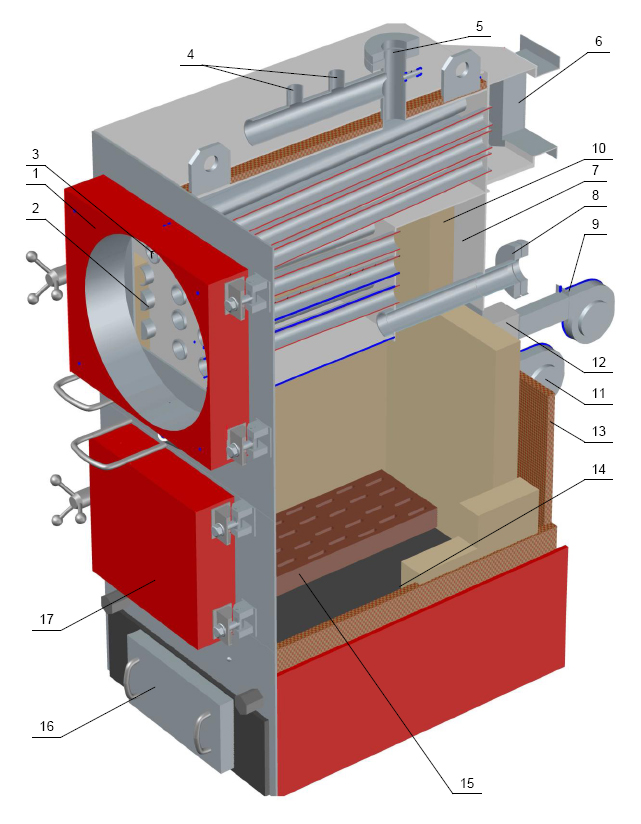
Fig 2