
Eurotherm KTH CE and KTH CE (T) gas floor coppers are intended for heat supply of the individual houses, apartments and constructions of household appointment supplied with systems of water heating with natural or compulsory circulatiaon of the heat carrier with the working pressure of water up to 0,3 MPas (3 bars) and the maximum water temperature at the exit from a copper to 80 C.
Gas floor coppers Evroterm KTN SE use air of the room in which they are established for burning (have the open combustion chamber). Withdrawal of products of combustion is made in a flue. The air flow and removal of combustion gases is performed naturally — at the expense of a difference of density. Coppers are supplied with stabilizers of draft and have the monitoring system of withdrawal of products of combustion.
Gas floor coppers Evroterm KTH CE(T) use air of the room in which they are established for burning (have the open combustion chamber). Coppers are supplied with stabilizers of draft and have the monitoring system of withdrawal of products of combustion. Withdrawal of products of combustion can be made in the isolated flue, a general flue or — is direct through the protecting building construction (a wall, a roof). Removal of combustion gases is performed compulsorily — due to operation of the smoke exhauster established after the draft stabilizer. Due to the depression which is artificially created in the furnace camera the air flow on burning from the room where the copper is established is provided.
Technical specifications
| Найменування параметр | Од. вим. | Найменування апарату | ||
|---|---|---|---|---|
| КТН 50 СР | КТН 100 СР | КТН1 100 СР | ||
| 1. Паливо | Природний газ ГОСТ 5542-87 | |||
| 2. Номінальна (мінімальна) теплопродуктивність | кВт | 48 (19) | 96 (19) | 96 (37) |
| 3. Витрати природного газу при номінальній (мінімальної) теплопродуктивності | м3/год. | 5,47 (2,1) | 10,94 (2,1) | 10,94 (4,2) |
| 4. Максимальна температура опалювальної води на виході з котла | °С | 80±5 | ||
| 5. Номінальний тиск газу | Па | 1960 | ||
| 6. Робочий тиск в системі опалення, в діапазоні | бар | 3…0,7 | ||
| 7. Діапазон регулювання температури опалювальної води на виході з котла | °С | 30….80 | ||
| 8. ККД, не менш | % | 92 | ||
| 9. Корегований рівень звукової потужності працюючого котла, не більш | дБ | 52 | 52 | 52 |
| 10. Номінальна температура продуктів згоряння на виході з котла, не менше | °С | 110 | ||
| 11. Усереднена витрата димових газів при номінальній тепло продуктивності | м3год. г/с | 128 30,4 | 256 60,8 | 256 60,8 |
| 12. Необхідне розрідження (тиск) в димоході за котлом, не менш | Па | 3 | 3 | 3 |
| 13. Номінальна напруга / частота електричного струму | В/Гц | ~220/50 | ||
| 14. Номінальна споживана електрична потужність | Вт | 10 | 20 | 10 |
| 15. Розміри приєднувальних патрубків: • по газу • опалювального контуру | дюйм | G½” G2″ | G½”-2 шт. G2″-2 пары | G¾” G2″ |
| 16. Діаметр патрубка димових газів | мм | 158 | 158-2 шт. | 218 |
| 17. Габарити: • висота • ширина • глибина | мм | 1161 626 740 | 1161 1326 740 | 1161 996 607 |
| 18. Зміст в сухих нерозбавлених продуктах згоряння: • СО₂ не більш • NOₓ не більш | мг/м3 мг/м3 | 119 240 | ||
| 19. Термін служби, не менше | років | 15 | ||
| 21. Маса апарату (без димоходу) | кг | 172 | 328 | 253 |
| *Зі знятою трубоприставкою | ||||
Газові підлогові котли Євротерм КТН СЕ. Автоматичні.
| Найменування параметру | Од. вим. | Найменування апарату | |||||
|---|---|---|---|---|---|---|---|
| КТН 50 СЕ | КТН 50 СЕ(Т) | ТН 100 СЕ | КТН 100 СЕ(Т) | КТН1 100 СЕ | КТН1 100 СЕ(Т) | ||
| 1. Паливо | Природный газ ГОСТ 5542-87 | ||||||
| 2. Номінальна (мінімальна) теплопродуктивність | кВт | 48 (19) | 48 (19) | 96 (19) | 96 (19) | 96 (37) | 96 (37) |
| 3. Витрати природного газу при номінальній (мінімальної) теплопродуктивності | м3/год | 5,47 (2,1) | 5,47 (2,1) | 10,94 (2,1) | 10,94 (2,1) | 10,94 (4,2) | 10,94 (4,2) |
| 4. Максимальна температура опалювальної води на виході з котла | °С | 80±5 | |||||
| 5. Номінальний тиск газу | Па | 1960 | |||||
| 6. Робочий тиск в системі опалення, в діапазоні | бар | 3…0,7 | |||||
| 7. Діапазон регулювання температури опалювальної води при виході з котла | °С | 30….80 | |||||
| 8. ККД, не менш | % | 92 | |||||
| 9. Корегований рівень звукової потужності працюючого котла, не більше | дБ | 52 | 55 | 52 | 55 | 52 | 55 |
| 10. Номінальна температура продуктів згоряння на виході з котла, не менш | °С | 110 | |||||
| 11. Усереднені витрати димових газів при номінальній теплопродуктивності | м3год. г/с | 128 30,4 | 128 30,4 | 256 60,8 | 256 60,8 | 256 60,8 | 256 60,8 |
| 12. Необхідне розрідження (тиск) в димоході за котлом, не менш | Па | 3 | (50) | 3 | (50) | 3 | (50) |
| 13. Номінальна напруга / частота електричного струму | В/Гц | ~220/50 | |||||
| 14. Номінальна споживана електрична потужність | Вт | 10 | 70 | 20 | 140 | 10 | 100 |
| 15. Розміри приєднувальних патрубків: • по газу • опалювального контуру | дюйм | G½” G2″ | G½” G2″ | G½”-2 шт. G2″-2 пары | G½”-2 шт. G2″-2 пары | G¾” G2″ | G¾” G2″ |
| 16. Діаметр патрубка димових газів | мм | 158 | 80 | 158-2 шт. | 80-2 шт. | 218 | 100 |
| 17. Габарити: • висота • ширина • глибина | мм | 1161 626 740 | 1161* 626 740 | 1161 1326 740 | 1161* 1326 740 | 1161 996 607 | 1161* 996 627 |
| 18. Зміст в сухих нерозбавлених продуктах згоряння: • СО₂ не більш • NOₓ не більш | мг/м3 мг/м3 | 119 240 | |||||
| 19. Термін служби, не менш | років | 15 | |||||
| 21. Маса апарату (без димоходу) | кг | 172 | 172 | 328 | 328 | 253 | 273 |
| * Зі знятою трубоприставко | |||||||
Device’s description and function
The scheme of air intake and withdrawal of products of combustion is provided on figure 1.
In figure 2 has provided the scheme of withdrawal of products of combustion for of floor gas coppers of KTH CE (T) to the isolated flue. Such scheme is applied to the intermediate gas flue (between a copper and a flue) with a high aerodynamic resistance (small diameter, a difficult configuration) and significantly facilitates designing conditions in the existing buildings.
In figure 3 have provided schemes of withdrawal of products of combustion for several of floor gas coppers of KTH CE (T) to a general flue. The general flue, at the same time, in case of all operating modes in all range of weather conditions (for providing GVS – that and during not heating period), shall provide steady depression in points of connection of gas flues from coppers.
In figure 4 have provided schemes of withdrawal of products of combustion for of floor gas coppers of KTH CE (T) through the protecting designs. Withdrawal of products of combustion through a wall (at the left in drawing) is possible for the process buildings, roof boiler rooms and cases provided by the existing standard rates. The bias of the gas flue shall be organized towards an exit through a wall. Withdrawal of products of combustion through a roof (at the left in drawing) is possible for a case of installation of a copper on upper floors or in the one-storey building. At the same time the gas flue length limit no more than 6 m shall be observed. And, each branch on 900 reduces this length by 0,75 m. Observance of this condition is caused by need to guarantee operation of the smoke exhauster in the range of necessary values of performance. The bias of a horizontal site of the gas flue shall be organized towards a copper. Withdrawal of products of combustion through eaves (in the middle in drawing) is possible for a case of installation of a copper on upper floors or in the one-storey building. The conditions limiting length of the gas flue and a bias of its horizontal sites – same, as for the previous case.
In figure 5 has illustrated the case forbidden to application for installation of coppers on lower floors of residential and public buildings – the installation of a floor gas copper of KTH CE (T) with removal of combustion gases through a wall. The installation of a floor gas copper of KTH CE (T) with removal of combustion gases through a wall on lower floors of process buildings can be admissible if the deaf facade is located above and there are no zones of stay of people. For this case it is necessary to provide, generally, a gas flue exit through a wall on a mark not lower than 2,2 m over pass level.
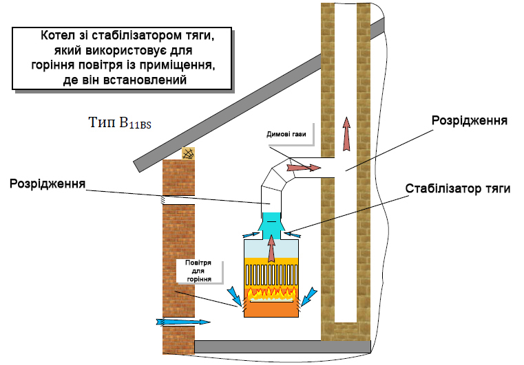
Fig 1
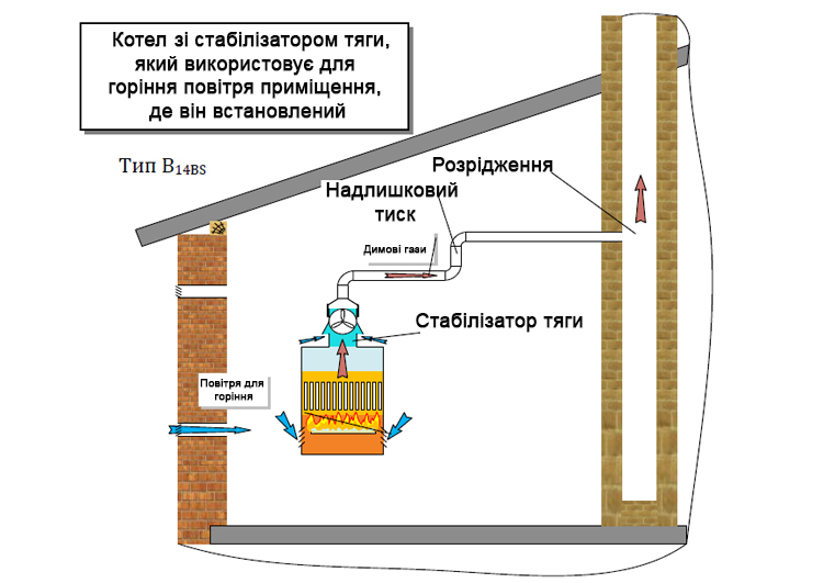
Fig 2
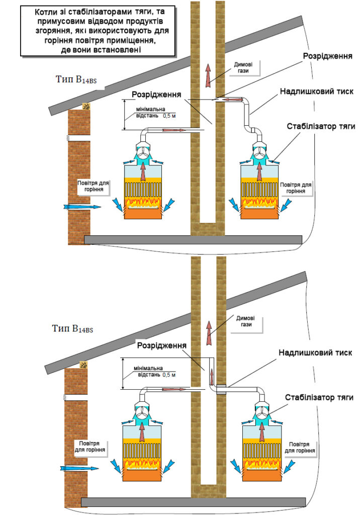
Fig 3
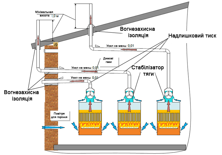
Fig 4
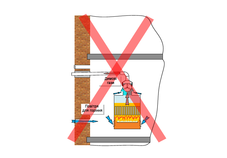
Fig 5